
Introduction: The Vital Role of Electrical Panels in Industry
In the modern industrial landscape, the electrical panel (or switchgear assembly) is recognized as the beating heart of energy distribution and control systems. The process of Electrical Panel Construction is not merely a simple mechanical procedure; it is a complex combination of precise engineering, adherence to strict safety standards, and the art of assembly. The goal of building a panel is to provide a secure and organized framework for housing protection, control, and power distribution equipment capable of stable performance under various environmental conditions.
The importance of this subject is amplified when we realize that the slightest error in design or assembly can lead to irreversible damages, both human (such as electrocution and arc flash) and financial (such as production line stoppages or equipment fires). Therefore, mastering the stages of construction, understanding equipment, and being aware of international standards like IEC 61439 is essential for every electrical engineer and technician. In this comprehensive guide, we will delve layer by layer into the electrical panel manufacturing process, from the conceptual phase to final delivery.
Phase 1: Design and Engineering
Before a single screw is tightened, the construction process begins with design. Designing an electrical panel requires a deep understanding of project requirements, load consumption, and environmental conditions.
Electrical Schematics
The first step is preparing the electrical drawings. Design engineers use specialized software such as EPLAN Electric P8 or AutoCAD Electrical to draw Single Line Diagrams (SLD) and multi-line schematics. In this stage, the method of motor starting (Star-Delta, VFD, or Soft Starter), the capacity of circuit breakers (MCCB/ACB), and the Control Circuit logic are determined. Precise calculations for busbar and cable sizing based on nominal current and short-circuit current are performed at this very stage.
Layout Design
Once the circuits are finalized, it is time for the physical Layout design. This stage involves the arrangement of components inside the panel enclosure (cell). The designer must consider sufficient space for cable routing, ducts, and breathing space for heat-generating equipment (such as inverters and power supplies). Failure to observe standard spacing at this stage can lead to thermal issues and difficulties in maintenance in the future.
Phase 2: Enclosure Selection and Metalwork
The selection of the appropriate enclosure is based on the installation environment (Indoor or Outdoor) and the required Ingress Protection (IP Rating). The panel body must be resistant to dust ingress, moisture, and mechanical impacts.
Material and Painting
Usually, galvanized or cold-rolled steel sheets with thicknesses of 1.5 to 2.5 mm are used for body construction. After cutting, bending, and welding, the body enters the painting phase. The use of Electrostatic Powder Coating with standard color codes (usually RAL 7032 or RAL 7035) is mandatory to guarantee resistance against corrosion and rust. The thickness of the paint and the quality of curing in the oven determine the panel’s lifespan.
Phase 3: Mechanical Assembly
In this stage, the internal Mounting Plates are prepared for equipment installation. Technicians, using layout drawings, install DIN Rails and slotted Cable Ducts onto the plate. Precision in leveling the rails and the tightness of connections is critical.
Heavy equipment like Air Circuit Breakers (ACBs) and transformers require chassis construction and mechanical reinforcements. Additionally, cutouts on the panel door for installing signal lights, Push Buttons, and HMI displays must be done with precise Punch tools to prevent sheet deformation and maintain proper sealing (IP).
Phase 4: Busbar & Wiring
This stage is perhaps the most sensitive operational part of electrical panel construction, requiring high skill and precision from the assembler.
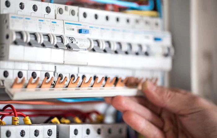
Busbar System
To transfer high currents (usually above 100 Amps), copper busbars are used instead of cables. Busbars must be calculated based on permissible current and, if necessary, insulated with Heat Shrink sleeves. Busbar connections must be secured with steel bolts, nuts, flat washers, and spring washers. The use of a Torque Wrench to ensure bolts are tightened to standard torque is mandatory to prevent overheating at connection points.
Control and Power Wiring
Wiring must be performed exactly according to the electrical schematic. Adhering to wire color coding (e.g., Black for power phases, Blue for Neutral, Yellow-Green for Earth, and Red for AC control) is a standard requirement.
Key points in wiring include:
Phase 5: Testing, QC, and Delivery
After assembly is complete, the electrical panel should not be shipped directly to the site. Performing Factory Acceptance Tests (FAT) is essential to ensure proper operation and safety.
Routine Tests
Conclusion
Electrical panel construction is a process that bridges engineering knowledge with technical skills. A standard, high-quality electrical panel not only guarantees energy distribution but also protects operator safety and the lifespan of expensive industrial equipment. Strict adherence to assembly standards, use of quality components, and rigorous QC testing make the difference between an ordinary panel and a professional, reliable one.